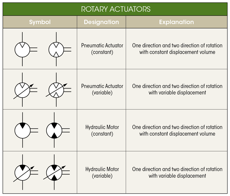
Hydraulic Electric Motor Symbol, 1 Hydraulic components symbols use of circuit symbols
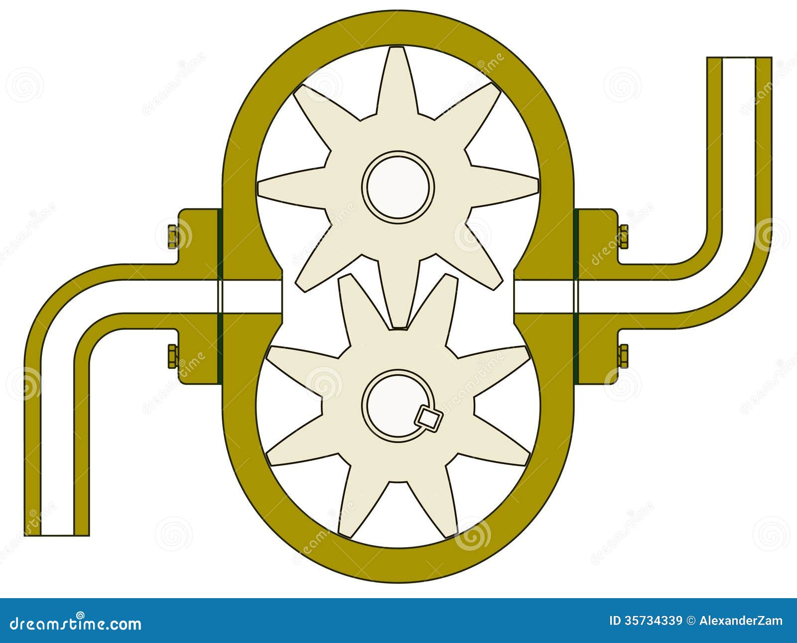
Gear pump is the positive displacement pump in which the suction is created by rotation and meshing of two gears. The fluid enters into the pump through the inlet and is transferred through the outlet port. It pumps the hydraulic fluid through two similar inter meshing spur gears, mounted in a casing, by displacement. Figure 1: Gear Pump.

Mechanical Drawing Symbols Process Flow Diagram Symbols Design elements Hydraulic pumps
P&ID stands for "Piping and Instrumentation Diagram" which is a detailed overview of processes with (P&ID) symbols itemising what equipment is used at each step within a process. Often there is more than one symbol available for a particular piece of equipment.
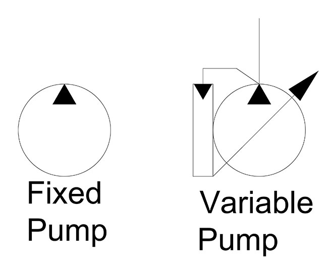
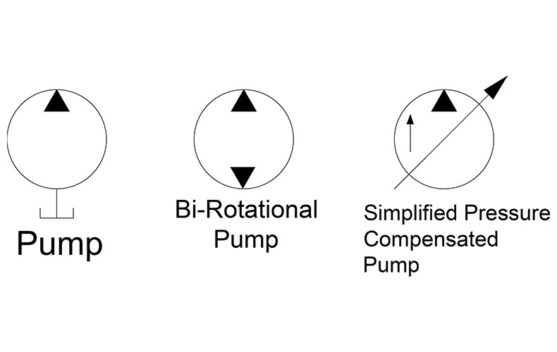
What is the difference between fixed and variable pumps?
Pre-drawn process and instrument diagram symbols like centrifugal pump, vertical pump, screw pump, bin and more help create accurate diagrams and documentation. Download. Pricing. Gear pump uses the meshing of gears to pump fluid by displacement. Motor is a device that creates motion. It usually refers to an engine of some kind.
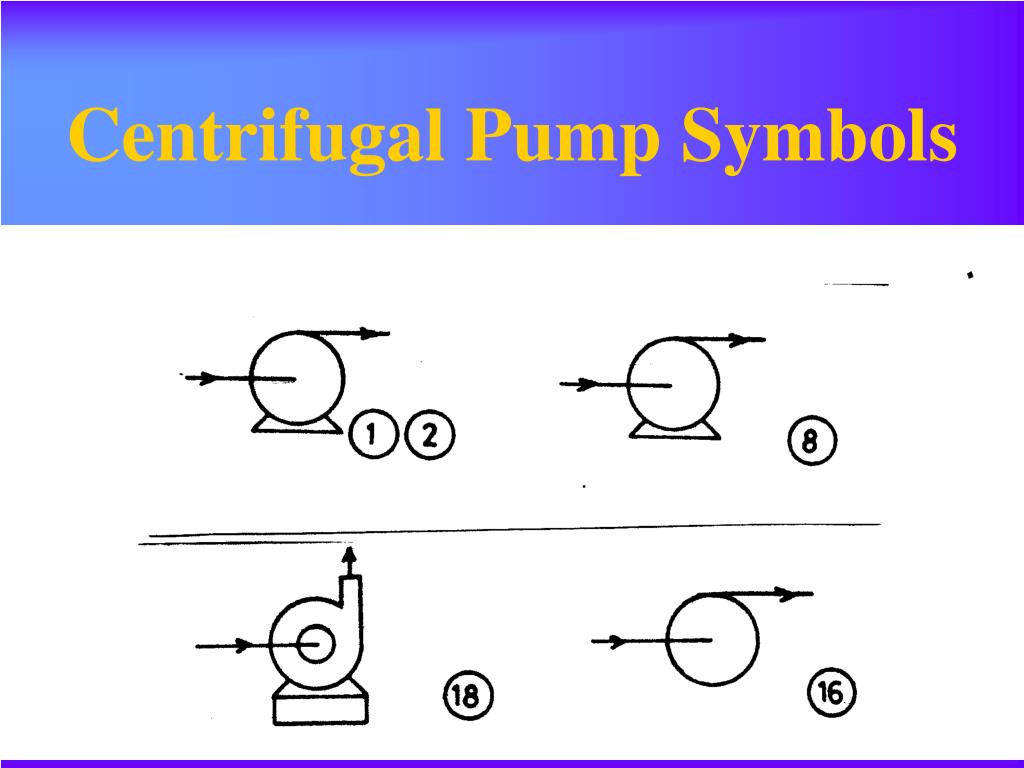
Centrifugal pump symbol icon Royalty Free Vector Image
Lesson 1: Gear Pump Basics Division of McNally Industries Northern Pump manufactures gear pumps that are positive displacement, rotary pumps, with two gears of equal size. The drive shaft and gear is rotated by a motor or by extension of a auxiliary motion shaft. The drive gear turns the driven shaft and gear. Drive Shaft

Industrial Valve and Actuator Symbols Process Control Solutions Blog Delivering Innovation
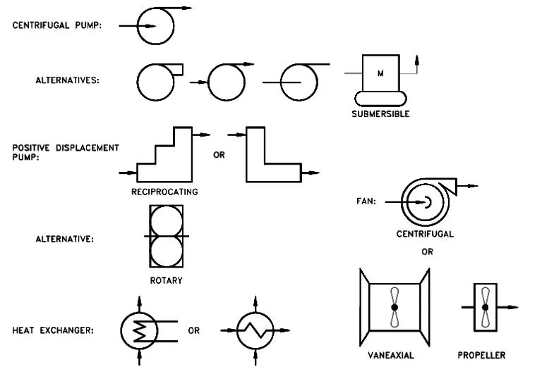
The most common P&ID symbols are listed below: lines piping components (pipes, flanges, and fittings) valves filters instruments and instrumentation pumps compressors vessels electrical machines (motors, generators, and turbines) heat exchangers LINES P&ID SYMBOLS PIPING P&ID SYMBOLS VALVES P&ID SYMBOLS FILTERS P&ID SYMBOLS INSTRUMENTS P&ID SYMBOLS
Symbole und Notation von R&Ischema Lucidchart
Symbols ∆. Lesson 2: Gear Pumping Terms. The rate of flow of a gear pump is the quantity of fluid actually delivered per unit of time, including both the liquid and any dissolved or entrained gases, at stated operating conditions. In the absence of any vapor entering or forming within the pump, rate of flow is equal

Schematic Symbol For Pump
A gear pump is a type of positive displacement (PD) pump . It moves a fluid by repeatedly enclosing a fixed volume using interlocking cogs or gears, transferring it mechanically using a cyclic pumping action. It delivers a smooth pulse-free flow proportional to the rotational speed of its gears.
PPT Piping and Pumping PowerPoint Presentation, free download ID333802
What is a Pump Schematic Symbol? A pump schematic symbol is a graphical representation used in electrical and mechanical engineering diagrams to represent a pump. It is a standardized symbol that allows engineers and technicians to quickly identify and understand the presence and function of a pump in a given system.

Hydraulic pump circuit symbols Part 2 YouTube
A gear pump uses the meshing of gears to pump fluid by displacement. [1] They are one of the most common types of pumps for hydraulic fluid power applications. The gear pump was invented around 1600 by Johannes Kepler. [2] Gear pumps are also widely used in chemical installations to pump high- viscosity fluids.

p&id symbols Edward Mills
Positive Displacement Pump 02 symbol: Positive Displacement Air 03 symbol: Proportionating Pump symbol: Pump 01 key: Reciprocating Pump 01 symbol: Reciprocating Pump 02 symbol: Rotary Gear Pump symbol: Rotary Pump symbol: Screw Pump 01 symbol: Screw Pump 02 symbol: Immersible Pump symbol: Sump Pump graphic: Turbine Pump icon: Vacancy Pump.
Hydraulic Schematic Diagram Symbols
Piping and Instrument Diagram Standard Symbols Detailed Documentation provides a standard set of shapes & symbols for documenting P&ID and PFD, including standard shapes of instrument, valves, pump, heating exchanges, mixers, crushers, vessels, compressors, filters, motors and connecting shapes. Or Gate Not Gate Correcting Element Diamond

P&ID and PFD Drawing Symbols and Legend list (PFS & PEFS)
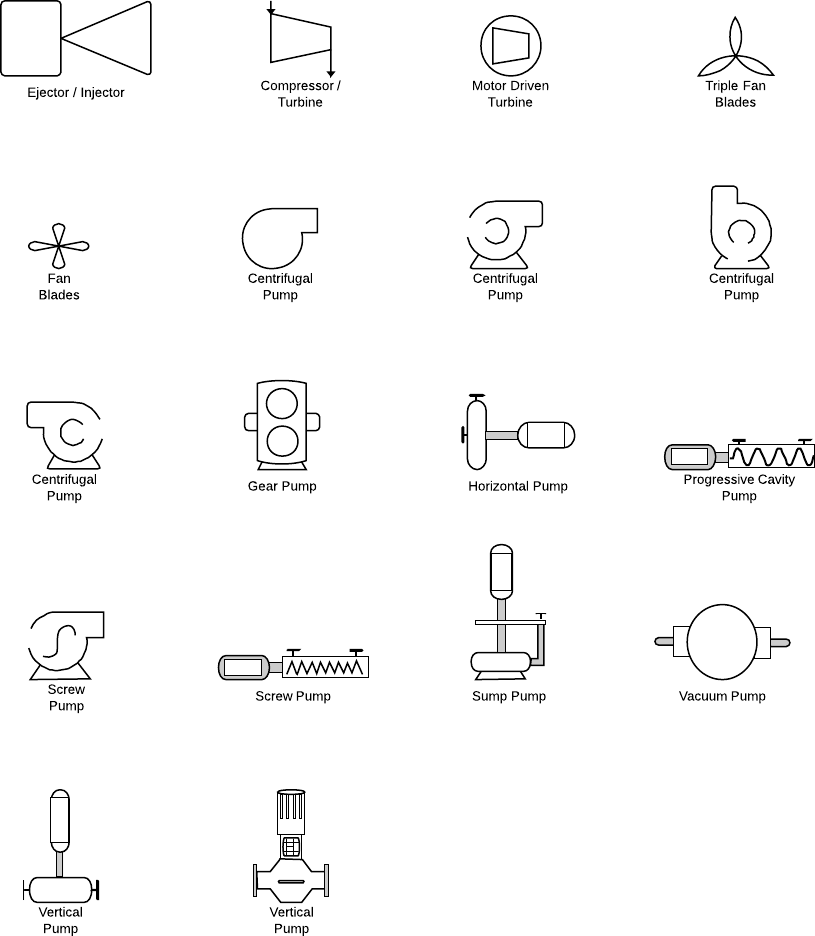
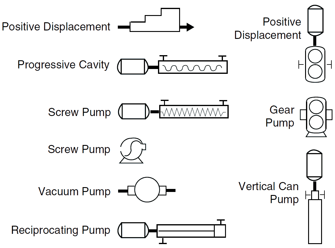
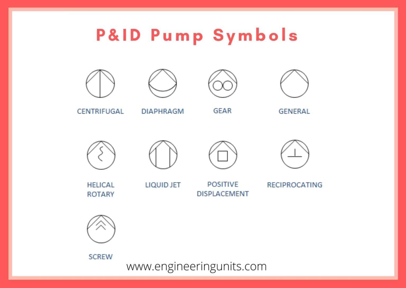
P&ID Symbols for Pumps Cavity Pump Centrifugal Pumps 01 Centrifugal Pumps 02 Centrifugal Pumps 03 Centrifugal Pumps 04 Centrifugal Pumps 05 Gear Pump Horizontal Pump ISO Centrifugal Pump ISO Diaphragm Pump ISO Gear Pump ISO Liquid Pump ISO Positive Displacement Pump ISO Progressive Pump ISO Screw Pump Liquid Ring Vacuum Pump Peristaltic Pump
Piping and Instrumentation Symbols Instrumentation Tools
There are few ISO and British standards available that provide symbols and best practices to draw PFD and P&ID, such as, ISA S5.1, BS 5070, and ISO 10628. Pumps and Turbine P&ID Symbols. The symbols for various types of rotary equipment such as a centrifugal pump, vacuum pump, and also positive displacement pumps such as gear and screw types.
Gear pump stock vector. Illustration of airengine, machine 35734339
Pump symbols in P&ID diagrams are used to represent different types of pumps used in process systems, such as centrifugal pumps, gear pumps, sump pumps, vacuum pumps, and screw pumps.
P & ID y PFD Drawing Symbols and Legend list (PFS & PEFS) Chad Wilken's
Gear Pump Terminology Gear Pump 101 Lesson 2: Gear Pump Terminology When your reputation depends on it! Northern® Lesson 2 Gear Pump Terminology ∆ Symbol Term Metric Unit Abbreviatio n US Customary UnitAbbreviatio n Conversion factor a A Area square millimeter mm2 square inches in2 645.2
How To Read P&ID , Basic And Advanced Knowledge?
The external gear pump is a positive displacement (PD) type of pump generally used for the transfer and metering of liquids. The pump is so named because it has two gears that are side-by-side or external to each other. (This nomenclature differen-tiates it from an internal gear pump, which has one gear positioned inside the other.)